Monday, February 4, 2019

Summer tweaks

The Corolla eFX has had Cycle Analyst 2.3 as its Ah meter for a long time but now I found time to install it's speed sensor to work. I found a suitable place for the speed sensor magnet from the driver side inner drive shaft joint.


I attached the magnet on a long cable tie using a suitable shrinking tube. Then attached the cable tie on the drive shaft joint as in the pictures above. Corolla's gearbox had a suitable place to close to the drive shaft joint to mount the speed sensor. With the speed sensor working, I now have a more accurate speed meter and also the delight of energy consumption (Wh/km) metering.


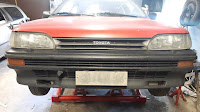
As overheating seemed not to be an issue, I wanted to test if closing all the car's front openings would make any difference. At least the car would get less dirt into its engine room. I made a new solid front grille from black painted acrylic sheet. All the bumper's opening were simply taped over using black gorilla tape. This solution has now survived well for about 7 months of driving, also during winter.


Seems that I had plenty of time last summer since I had tried to even restore the car's paint :)


10,6 kWh/100km was Corolla's last summer's consumption record. In Corolla's circuity only the traction battery consumption is measured by the Cycle Analyst so lights, radio etc. would need to be added in the result. Assuming 200W for them would add roughly 0,1 kWh in this half hour run so the total consumption still remained under 11 kWh/100km at best. During summer time the Cycle Analyst typically gives me 11-13 kWh/100km readings, with my average speeds of less than 50km/h. 80 km/h goes with around 15-16 kWh/100km :)


Friday, April 6, 2018

Corolla eFX is back on duty!

It was an exiting drive into the inspection as I had only test driven the car on our yard. I was more than happy to drive with the car's new electric drivetrain, it worked just like planned! It has only a few kW more peak power available than with the burnt ME1003 motor but the full 26kW is now available with much wider RPM range making driving very pleasant. There's just no need to shift the gears:)

The first drives were very careful as I kept a close eye on how the component temperatures behaved. It was a 0C day and the SR250V500A-V2's IGBT-module temperature sensor peaked at 51C, which is just above where I've set the controller's cooling fan to start. The K9HV motor's highest temperatures remained at 30C max. The temperature rise seem to be quite well under control.

The yearly inspection went well without any notices and now the car will face all my daily driving needs again after resting for about 10 months, hope it works this well for years to come:)

Monday, April 2, 2018

Finishing the electric drivetrain update

There was quite a list of tasks that I wanted to do before the Corolla would be back on the roads. These included: 
  • Adding a second charger
  • Adding an emergency stop button
  • Finishing the motor controller assembly
  • Modifying the Cycle Analyst for higher voltage
  • Revising all electrics
  • Adjusting the controller software
  • A lot of testing

Here's Corolla's newest main circuit diagram revealing the car's current electric drivetrain in full.


I started to tackle my task list by mounting the emergency stop button and the second charger. The emergency stop button simply disconnects the traction battery pack with two Gigavac GV200 contactors. The added second charger was identical to the first Powerfinn PAC-800 charger. Now each 24S LiFePO4 battery pack have their own charger. In the picture above also the motor controller's display can be seen located next to the Cycle Analyst.


The next task was to find a suitable place for the Gigavac GV200 contactors. I chose to mount them under the rear battery pack. Moving to a higher battery voltage required new fuses rated accordingly. My choice for the traction battery fuses were NH1 type 250A fuses rated to 440Vdc. For the smaller current high voltage fusing needs I chose 6,3x32 ceramic fuses rated to 400Vdc.


My next job was to update the motor controller assembly. The pictures above show the result. I used Meanwell MDR-series Din-rail power supplies as isolating DC-DC power supplies. The bigger one provides 12V to the Motoc SR250V500A-V2 controller, Pre-charge contactor and a 12V 20W fan. The smaller one powers the Cycle Analyst after modifying it to measure voltages up to 300Vdc (to be future proof :)


This is how the Kostov K9HV looks below just before placing the bottom covers. I think the K9HV is a good fit for the Corolla:)


The next step was to remove the 72V system electrics and build it up again to support 144V voltages. The changes were not big but I had to make changes into every enclosure that the Corolla had so it took quite a while.

No project comes without problems. This time I made a mistake by carelessly connecting the charger into the rear battery pack. While making the connection to the cell terminal I was unlucky to have the chargers connection inrush current flowing through the SBM circuit board. As a result the balancing control IC and mosfet were shorted on the SBM's most upper cell circuity. This caused a few weeks timeout as I had to figure out how to fix the fault. I was not able to source the broken unknown Chinese components used in the SBM (marking R2RP) so I decided to replace the balancing controller IC with a LMV421 circuit. My LMV421 circuit ended up having quite much higher leakage current than the original balancing control IC. To prevent serious unbalance problems due to differences between different cell circuity leakage currents I decided to match each cell's circuit leakage current by applying suitable sized shunt resistors on them. After careful testing I am convinced that the SBM is again working as expected and I mounted it back to work.


After all needed changes were done, it was time to cover up everything. This is how the Corolla looks under the hood at the moment.

Time for test drive! It's always nice to make test drives and even more so when there is more power available than before:) Some PI-controller parameter iterations later I got a result where the throttle response is instant without any oscillation. The DC-link current limit (set to 200A) seems also work accurately as can bee seen on the Cycle Analyst display showing the highest current draw and lowest battery voltage resulting in close to 27kW power! The smaller display shows some information that I wanted to be displayed from the Motoc SR250V500A-V2 controller. The upper row shows temperatures of the XMC1302 microcontroller, motor thermistor and IGBT-module's thermistor. The lower row displays current DC-link voltage and motor current.

The Corolla is now ready for its yearly inspection to be road legal again after 10 long months! The K9HV motor and SR250V500A-V2 controller have changed the car from sluggish to more like a normal car. Despite of a rather small increase in peak power (from around 21kW to 27kW) the new drivetrain provides the available power in a far broader RPM range than with the ME1003 motor and Kelly Controller. With the K9HV motor I can drive up to 93km/h using just the second gear, which I hope will make my daily driving just like it should with an EV; no more gear shifting:)

Sunday, December 31, 2017

First test drive with K9HV and its new controller

To make sure that the new motor installation works properly I decided to build the car ready for a test drive with its current battery voltage of 76,8V. There was only a few things to finish up before the first meters could be driven with the Kostov K9HV motor installed.


Rebuilding the motor controller caused lack of space in its enclosure so the throttle pedal could not be located there anymore. The solution was to replace Corolla's original throttle pedal with a hall throttle. The hall pedal was mounted in a holder made from steel tube. The throttle pedal cable stays well protected inside the holder.

Now all that was left was to mount and connect the new SR250V500A-V2 motor controller and drive!

After a half year of staying inside the garage the Corolla finally got some fresh air:) It was exciting to test both the motor and also its new controller. The first notices were that the motor mounting had succeeded much better than with the ME1003, I could hear the motor RPM, but I could not feel its vibrations, excellent!

The controller worked also as well as I could have hoped for. The maximum power draw was 15kW just as it should with this battery voltage and the controller's current settings. That maximum power should nearly double after setting Corolla's front and rear battery packs in series, resulting into a battery voltage of 153,6V. There was also plenty of torque available. It was a slippery day and the drive wheels started to slip with any higher than 200A motor current on 2nd gear.

There is always something needing improvement; slight oscillation occurred during a slow acceleration. This is most likely caused by too high gain parameters in the motor controllers current PI-controller. These parameters will be tuned after the Corolla's battery voltage has been doubled. Knowing that the basics are ok with these voltages I can now start making the changes needed to double the voltage being more suitable to the K9HV motor.

Saturday, October 28, 2017

Fitting the Kostov K9HV into Corolla's gearbox


I had to build a new flange to mount the K9HV into the gearbox. The flange should be at least 30mm thick to prevent the motor axle from touching the gearbox axle. I had some 8mm thick aluminium scrap sheets available for the job, so I decided to attach two such sheets together forming a 16mm thick sheet. The flange would be constructed from two plates, one 16mm plate would be mounted to the motor and an other 16mm plate into the gearbox allowing me to adjust their alignment. I started by making a model from cardboard for the gearbox plate.


Using the cardboard models I cut the gearbox plate using a jigsaw.


Locating the holes to drill was a challenge. I decided to try pressing the plate against the gearbox with some Blu-Tack in between so the hole locations would get visible. This actually worked out well. I started by making two alignment pins that the original motor had as well. After the locating pins were made it was simple to locate one hole at the time to be drilled.


Once all holes were drilled, the gearbox plate could be mounted into its final location. Now the challenge was to get the gearbox axle aligned with the motor. I decided to build a special divider tool that allowed me to draw an accurate circle matching the K9HV motor's diarmeter. This would help me to make a first rough alignment.


Next I decided to build the motor's plate. I used countersunk bolts to mount the plate on motor allowing the motor plate to be pressed directly on the gearbox plate.


The motor plate was built with the same width as the motor's diameter so I was able to locate the motor plate mounting holes quite accurately on the gearbox plate using the circle drawn earlier with the divider. I made the motor plate's holes 2mm bigger than its bolts allowing me to fine tune the alignment of the motor and gearbox axles. The fine tuning would be completed by adjusting three stop screws forcing the location of the motor plate from its bottom, left and right sides.

The motor plate's mounting bolts threads were reinforced using helicoils. These four bolts will need to carry the motor and its torque so I did not trust bare aluminium threads.


Now I had all the components ready for finishing the assembly!


First the motor plate was mounted into the motor securely using plenty of thread lock.


Then the gearbox plate was mounted roughly on its place to be aligned later.


Next I assembled the flywheel and clutch. I used a torque wrench and thread lock in all places applicable.


Finally I got to fit the motor in its place and bolt the gearbox plate securely. Then it was time to adjust the motor and gearbox axle's alignment. I had no idea how I could confirm a good enough alignment so there was a lot of trial and erroring to do. Pretty soon I noticed that when I rotated the motor by hand I could hear a quiet creak as the clutch disk was forced to move due to misalignment of the two axle's. I then adjusted the motor plates location in respect to the gearbox plate until there was no creaking sound at all. I figured this alignment is as good as I would get and lock screwed the plates together so they would not move anymore.

To make sure the motor was properly mounted, I connected the motor into its controller and gave it a spin. I was really happy with the result, there is clearly less alignment and balancing error than I had with the former ME1003 motor's mount:) This motor will drive the Corolla smoothly!
  

Placed the original shields on the motor and now it's ready to be lifted in the car:)


Sunday, October 22, 2017

Preparing the Kostov K9HV motor

The K9HV was purchased pre used so I inspected it through before mounting it. The picture above shows my first setup that was able to spin the motor. The controller in the picture was the first prototype of Motoc - SR250V500A that will be developed to feed Corolla's motor. This setup got the motor to spin nicely.

A closer look to the bearings revealed a worn bearing housing. The smaller diameter axle side of the motor had about 0.5mm play between the bearing and the bearing housing. This was going to be fixed.

The motor's rear flange was removed so that the bearing housing could be repaired. The ball bearing seemed ok, but it got replaced with a new one just in case.


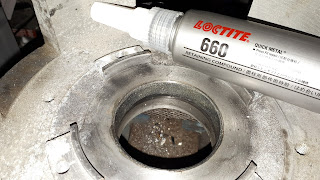
Cleaning the bearing housing revealed clear signs of wearing. Reviewing different methods to fix the worn bearing housing, I decided to purchase a bottle of Loctite 660 from eBay and give it a try. First I punched some marks in the worn bearing housing to help aligning the new bearing better in the center. Then I applied plenty of  Loctite 660 into the bearing housing before mounting a new ball bearing into its place. Carefully removed the excess Loctite so it wont get in the bearing, I think I got it fixed :) After a couple of days I checked the result and there is now a new bearing installed without any play on its bearing housing, success!


My next challenge was to mount Corolla's old flywheel into the motor shaft. That turned out to be easy as I only had to purchase a 1210 taper lock bush with a suitable bore to K9HV's shaft. www.bearingboys.co.uk had just what I needed once again!

With a new taper lock bush I got my old flywheel mounted and I decided to check how it was aligned. Measuring from the clutch plate surface I got nearly 0,3mm difference on one full rotation. I concidered this as too much so I gently sanded the taper lock bush so that it would compensate the alignment error. After a few trial and errors I settled with and error of 0,06mm. This step is done:)


Last but not least it was time to balance the motor with its flywheel on the shaft. With first rotations it became clear that there was some imbalance that could provide uncomfortable vibrations. As this motor will be rotated close to 2x higher speeds that its predecessor I was ready to offer some time to get the flywheel balanced.

The balancing method used was very simple trial and error, using neodymium magnets on the flywheel and determining where to drill off some material to improve the balance. Having drilled four quite big holes I could no longer determine any improvement so I considered the balancing step done. While balancing with this method I had some flying magnets in my garage when I rotated the motor too high. Although handy to use, I would not recommend using magnets this way for balancing flywheels due to safety.

Now the motor was rotating nicely up to very high speeds, so I am ready to start fitting the motor into Corolla's gearbox :)